AIR-TO-WATER (A2W) HEAT PUMPS DETAILS
Components of an Arctic heat pump system
There are three main components:
Heat pump
Buffer tank
Emitters (radiant heat etc)
Heat Pump
HEAT MODE
The buffer tank is heated by a heat pump (but it could also be a boiler or solar heating panel). In this case the target temperature of the buffer tank is 120 F.
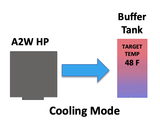
COOL MODE
Or, a heat pump can operate in cooling mode The buffer tank target temperature is shown at 48 F:

Even though we talk a lot about heat pumps, the place this discussion starts is at the BUFFER TANK.
Buffer Tank
The buffer tank is the center of the system; a thermal battery, as it stores either warm energy or cool energy (liquid).
A buffer tank is filled with freeze-protected non-toxic glycol and has at least four ports
Two ports (left in this case) are connected to the heat source which is the outdoor-mounted heat pump, and usually a back-up heat source (for temps below -15F)
The other two ports (right side of tank) are connected to the house distribution (e.g. radiant floor) to warm (or cool) the house
Buffer tank size typically ranges from 40 to 80 gallons

Hydronic Emitters to Distribute Heat

Then we add the emitters, such as a radiant floor to heat or cool the house.